
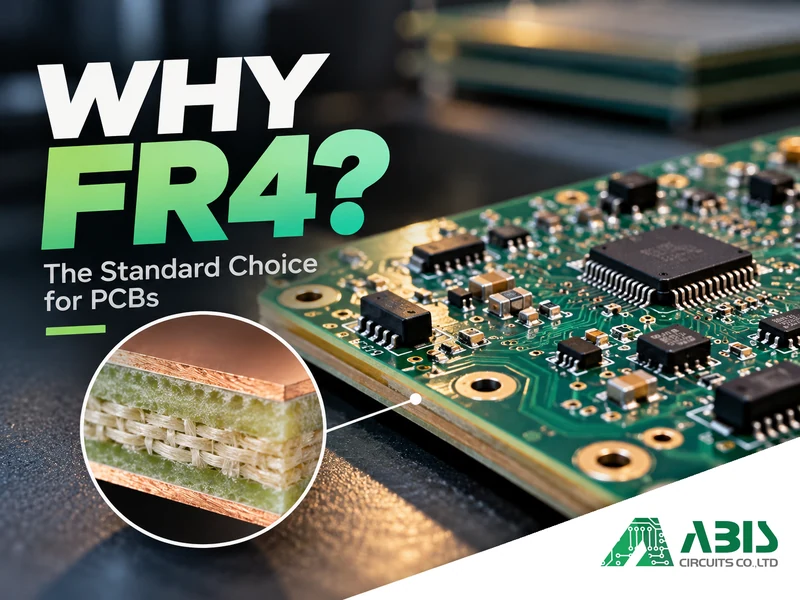
FR4(Flame Retardant 4)remains a standard choice, it offers a reliable balance of mechanical strength, electrical insulation, flame resistance, and manufacturing compatibility. Its widespread availability and compatibility with established fabrication processes also make it a practical, cost-effective material for everything from consumer electronics to industrial control systems.
Still, not every FR4 laminate performs the same way, and some PCB designs demand more than standard FR4 can offer. Understanding why manufacturers rely on FR4, which properties matter most, and where its limitations begin can help you choose the right material for your project.
What Is FR4 Material in PCB Manufacturing?
FR4 is a flame-retardant, glass-reinforced epoxy laminate commonly used as an insulating substrate in rigid printed circuit boards. It refers to a family of materials rather than a single laminate with identical electrical and thermal properties.
What Is FR4 Made Of?
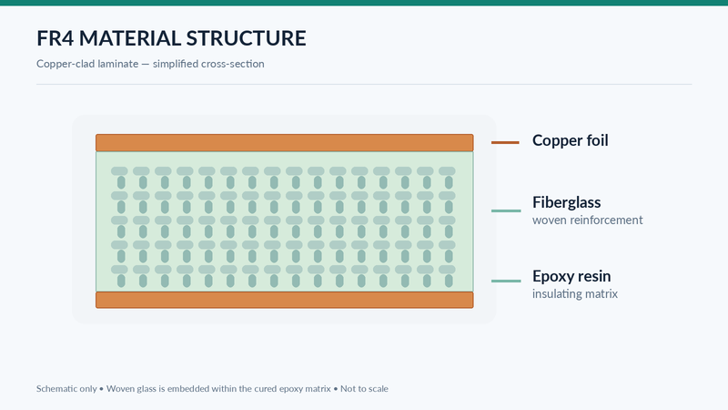
FR4 consists of woven fiberglass cloth impregnated with epoxy resin. The fiberglass provides mechanical reinforcement, while the cured resin holds the structure together and contributes electrical insulation. This combination gives FR4 the rigidity needed to support copper circuits and electronic components under normal manufacturing and operating conditions.
Flame Retardant means the material is formulated to meet specified flammability requirements, although its exact performance depends on the selected laminate grade.
How Is FR4 Used in a PCB?
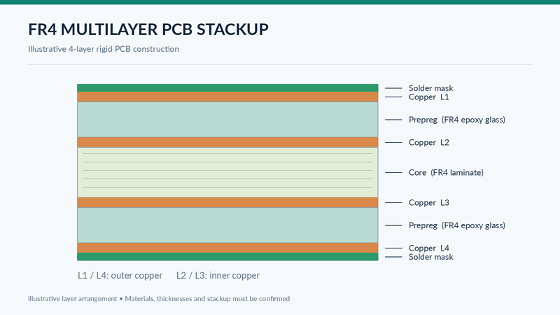
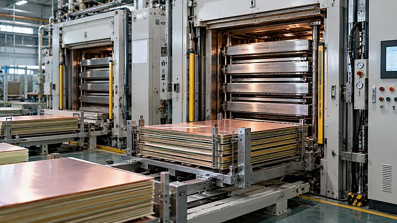
In PCB fabrication, copper foil is bonded to an insulating laminate to form a copper-clad core. Manufacturers then use processes such as imaging and etching to create conductive circuit patterns. For multilayer PCBs, FR4-based cores and resin-impregnated fiberglass prepreg are laminated together, bonding the layers while maintaining electrical insulation between them.
This construction makes FR4 suitable for a wide range of rigid PCB designs, from simple double-sided boards to multilayer PCBs with plated through-holes, controlled impedance, and dense component layouts.
Why Is FR4 Widely Used in PCB Fabrication?
There’s no single property that makes FR4 so widely used. Its real strength comes from how well its mechanical, electrical, and thermal characteristics work together.
For most conventional rigid PCBs, manufacturers need a material that provides dependable insulation, supports electronic components, and can move through established production processes without unnecessary complexity. FR4 meets these requirements remarkably well.
Mechanical Strength and Dimensional Stability
The woven fiberglass reinforcement gives FR4 considerable rigidity and helps it maintain dimensional stability during PCB fabrication and assembly. This matters when a board needs to support surface-mount components, connectors, and other electronic parts without excessive deformation.
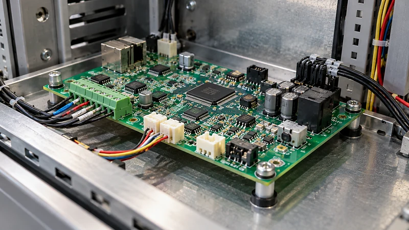
Think about a typical industrial control board. It may contain several connectors, larger components, and mounting points, all of which place mechanical demands on the substrate. FR4 provides a stable foundation for these components during normal handling, transportation, and operation.
Its rigidity also helps during drilling, copper patterning, and multilayer lamination. Of course, mechanical strength isn’t the same as flexibility. FR4 is designed for rigid boards, not applications that require repeated bending or folding.
Electrical Insulation and Dielectric Performance
A PCB needs to keep electrical signals traveling along the intended copper paths rather than through the substrate. FR4 provides electrical insulation between traces and conductive layers, making it suitable for many conventional electronic circuits.
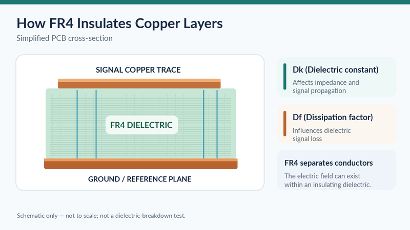
Its dielectric constant (Dk) is commonly around 4, although actual values vary with resin formulation, fiberglass content, operating frequency, and testing conditions. For many digital, analog, and control circuits, FR4 offers sufficient dielectric performance without requiring specialized high-frequency materials.
Still, Dk is only part of the picture. In high-speed and RF designs, dissipation factor (Df), transmission length, and trace geometry also affect signal integrity. For example, Isola’s 370HR laminate provides published dielectric and thermal characteristics that show why checking a specific material datasheet is more useful than assuming every FR4 laminate behaves identically.
Flame Resistance and Thermal Stability
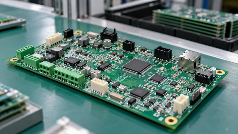
FR4 includes flame-retardant systems that help it meet specified flammability requirements. This is an important characteristic for electronic equipment, where substrate materials must meet applicable safety requirements.
Many FR4 grades can also withstand the thermal demands of conventional PCB manufacturing and assembly, including lead-free soldering when the selected laminate is suitable.
One distinction is worth remembering: flame resistance ≠ high-temperature reliability. A laminate may meet a flammability requirement but still be unsuitable for repeated soldering cycles or prolonged exposure to elevated temperatures. That’s why thermal expansion, glass transition temperature, and resistance to degradation need to be evaluated separately.
Compatibility with Standard PCB Manufacturing Processes
FR4 works well with established FR4 PCB fabrication processes, including drilling, copper plating, imaging, etching, solder mask application, and multilayer lamination.
Because manufacturers have extensive experience processing glass-reinforced epoxy laminates, FR4 is practical for both prototypes and volume production. Different laminate grades, thicknesses, and compatible prepreg materials are also widely available, giving manufacturers more flexibility when planning production.
This doesn’t mean every FR4 board is easy to manufacture. Complex stackups, tight tolerances, and demanding hole structures still require careful process control. But the familiarity and availability of FR4 make it a dependable starting point for many projects.
A Practical Balance of Performance and Manufacturing Cost
FR4 isn’t necessarily the cheapest material in every situation, but its established supply chain and compatibility with standard PCB processes often provide a good balance between performance and manufacturing cost. Specialized laminates may offer better performance in particular areas, such as lower dielectric loss or greater thermal resistance. The question is whether your PCB actually needs those properties.
If a suitable FR4 grade already meets the design requirements, choosing a more expensive substrate may add cost without providing a meaningful advantage.
Engineering Insight: Why FR4 Is Often the Starting Point
When evaluating PCB materials, a useful first question is: What does this board actually need to withstand?
Take a conventional industrial controller. Its main requirements may involve mechanical support, reliable insulation, standard assembly compatibility, and stable operation under normal conditions. If an appropriate FR4 grade meets those needs, there’s little reason to move directly to a specialty laminate. Good material selection is about meeting the application’s requirements, not choosing the material with the longest list of impressive specifications.
Key FR4 Material Properties Engineers Should Consider
Here’s where material selection becomes a little more interesting. Two PCB laminates can both be labeled FR4 yet behave differently during manufacturing or operation.
For a straightforward design, a standard material specification may be enough. But if your PCB involves demanding assembly conditions, complex plated holes, or special insulation requirements, the details matter.
Glass Transition Temperature (Tg)
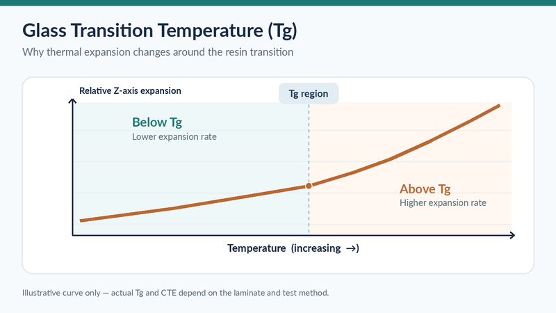
Glass transition temperature (Tg) describes the temperature region where the cured resin changes from a relatively rigid, glass-like state to a more flexible, rubber-like state. Conventional FR4 materials often have Tg values around 130–140°C, while higher-Tg grades may reach approximately 170°C or above, depending on the material and measurement method.
Why does this matter? As the laminate passes through its Tg region, its mechanical behavior and thermal expansion characteristics can change significantly. This becomes relevant during high-temperature manufacturing processes, particularly lead-free soldering.
Lead-free assembly may expose a PCB to peak temperatures around 245–260°C. At first glance, that seems far above the Tg of many FR4 materials. But exceeding Tg doesn’t automatically mean the board will fail.
What matters is the complete thermal exposure: how long the board stays hot, how often it experiences soldering cycles, and how the laminate responds to expansion and thermal stress. A higher Tg can be helpful, but it doesn’t tell the whole reliability story.
Z-Axis Coefficient of Thermal Expansion (Z-CTE)
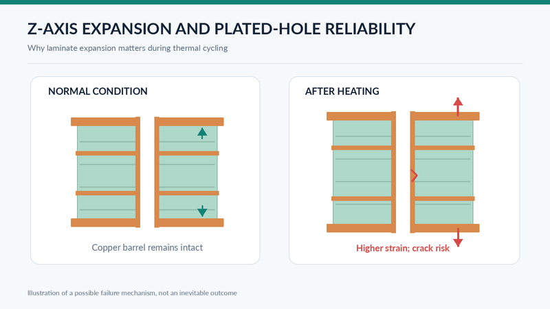
Materials expand when heated, and FR4 is no exception. The coefficient of thermal expansion (CTE) describes this behavior.
In FR4, woven fiberglass helps restrict expansion along the X and Y directions. Expansion through the board thickness—the Z-axis—is generally more significant, particularly once the material exceeds its Tg.
This becomes important when a PCB contains plated through-holes. As the laminate expands and contracts, the copper plating inside these holes must accommodate the movement. Excessive thermal strain over repeated cycles can contribute to copper fatigue, barrel cracks, or intermittent electrical connections.
The concern is greater in certain thick multilayer boards and high-aspect-ratio plated-hole structures. As NCAB Group explains in its material selection guidance, materials with similar Tg values can still show different thermal expansion characteristics. That’s one reason Z-CTE deserves attention rather than relying on Tg alone.
Decomposition Temperature (Td) and Delamination Resistance
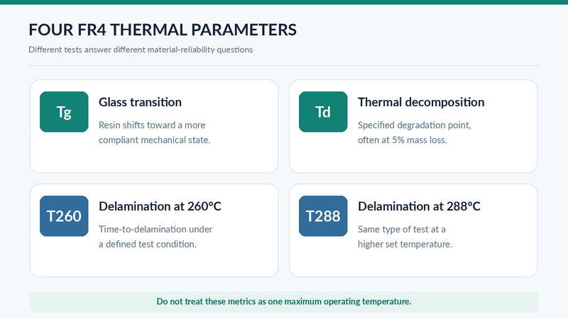
Decomposition temperature (Td) indicates the temperature at which a laminate reaches a specified level of thermal degradation, commonly measured at 5% weight loss under defined test conditions.
It’s tempting to assume that a higher Td automatically means better resistance to high-temperature assembly. In practice, there’s more to consider. A PCB may experience several heating cycles during double-sided SMT assembly or rework, and resistance to delamination is another important part of the evaluation.
This is where T260 and T288 become useful. These measurements describe time to delamination under specified elevated-temperature test conditions, helping engineers assess how a material responds to thermal exposure.
For example, Isola 370HR publishes Tg, Td, Z-axis expansion, and time-to-delamination data. Looking at these properties together provides a more meaningful picture of thermal reliability than comparing a single temperature value.
Comparative Tracking Index (CTI)
Comparative Tracking Index (CTI) measures how well an insulating material resists electrical tracking across its surface under standardized test conditions.
Electrical tracking can occur when moisture and contamination help form conductive paths along an insulating surface. This makes CTI especially relevant for certain high-voltage circuits, power electronics, and equipment operating in environments where surface contamination may be present.
A higher CTI rating can be valuable, but it doesn’t remove the need for proper creepage and clearance design. Nor does every industrial PCB require a CTI rating of 600 V or higher.
Generally, the appropriate value depends on the working voltage, pollution degree, applicable safety standards, and the insulation design itself.
Engineering Insight: Why “FR4” Alone May Be an Incomplete Specification
Writing “FR4” on a fabrication drawing may be sufficient for some conventional designs, but it doesn’t communicate every material requirement.
For example, a multilayer PCB exposed to repeated thermal cycles may need closer attention to Tg, Z-CTE, Td, and delamination resistance. A high-voltage board may introduce additional CTI requirements. Before production, it is worth reviewing these properties alongside the stackup and assembly conditions, then specifying the critical characteristics or an approved laminate grade where necessary.
What Are the Limitations of Standard FR4?
With so many advantages, it’s reasonable to ask why every PCB isn’t made from FR4.
The answer is that FR4 is designed to provide balanced performance, not exceptional performance in every category. When electrical losses, heat transfer, or thermal stress become more demanding, standard FR4 may no longer be the best option.
Signal Loss in High-Frequency and High-Speed Designs
Standard FR4 generally has higher dielectric loss than laminates developed specifically for high-frequency applications. As operating frequency, transmission length, or data rate increases, that loss may become significant enough to affect signal integrity.
The dissipation factor (Df) indicates how much electromagnetic energy is lost within the dielectric material. A lower Df is often desirable when minimizing transmission loss is important.
Does that mean FR4 becomes unusable above a particular frequency? Not necessarily. A short signal path at several gigahertz may behave differently from a much longer interconnect operating at the same frequency. Insertion loss, channel length, trace geometry, and the selected laminate all influence the decision.
Limited Thermal Conductivity
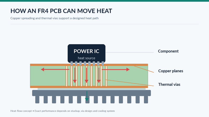
FR4 is not particularly effective at conducting heat compared with metals used for heat spreading. For most general-purpose circuits, this limitation can be managed through appropriate PCB design. But when components such as high-power LEDs or MOSFETs generate concentrated heat, the thermal path becomes much more important.
Additional copper, thermal vias, heat sinks, or an alternative substrate may be needed. The important point is to evaluate the complete heat-transfer path rather than judge the board solely by its substrate material.
Material Stress Under Demanding Thermal Conditions
Copper and laminate materials don’t expand at exactly the same rate. When a PCB experiences repeated heating and cooling, that difference can create mechanical stress within the board.
Depending on the material and construction, repeated thermal exposure may contribute to plated-hole fatigue, laminate degradation, or delamination. The risk becomes more relevant in products with demanding operating temperatures or frequent thermal cycling.
Rather than relying on a general temperature limit for all FR4 materials, engineers should check the selected laminate’s thermal characteristics against the actual operating and assembly conditions.
When Should You Choose an Alternative?
FR4 is a practical choice for many rigid PCB designs, but there are situations where a specialized material is worth considering. The right alternative depends on the problem you’re trying to solve.
| PCB Material | Main Advantage | Typical Selection Reason |
|---|---|---|
| Standard FR4 | Balanced electrical and mechanical properties | General-purpose rigid PCB designs |
| High-Tg FR4 | Higher glass transition temperature | More demanding thermal requirements |
| Low-loss RF/high-speed laminates | Reduced dielectric loss | High-frequency or high-speed signal integrity |
| Metal-core PCB | Improved heat-transfer structure | Concentrated heat-generation applications |
| Polyimide-based laminates | Specialized thermal performance | Certain demanding high-temperature environments |
These are general comparisons. Actual performance still depends on the laminate grade, stackup, and operating conditions.
When Do High-Frequency Designs Need Low-Loss Materials?
If signal loss becomes a major design constraint, low-loss laminates may offer an advantage over standard FR4. These materials are engineered to provide lower dissipation factors and more controlled dielectric properties, helping reduce transmission losses in demanding RF and high-speed applications. For example, the Rogers RO4000 series datasheet lists a typical Df of 0.0037 at 10 GHz for RO4350B.
That doesn’t mean every PCB operating at 10 GHz needs this material. The real question is whether your design’s signal loss budget can tolerate the characteristics of the proposed laminate. If it can, FR4 may still be a reasonable option.
When Is a Metal-Core PCB Better for Heat Dissipation?
For circuits that generate substantial localized heat, a metal-core PCB may provide a more suitable structure. A typical aluminum-based PCB combines a copper circuit layer, an electrically insulating but thermally conductive dielectric layer, and a metal base that helps transfer heat toward the cooling system.
One detail is easy to overlook: the thermal conductivity of the dielectric layer is not the same as that of the aluminum core. The board’s actual thermal performance depends on the entire structure.
Metal-core PCBs are often considered for power LEDs and certain power electronic assemblies. However, FR4 can still be suitable when copper planes, thermal vias, and external heat sinks provide enough cooling.
When Should You Consider High-Tg FR4 or Polyimide?
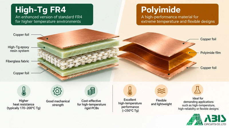
High-Tg FR4 may be worth considering when assembly or operating conditions create more demanding thermal requirements. It can offer different thermal expansion characteristics, but higher Tg alone doesn’t guarantee better reliability. Td, Z-CTE, and delamination resistance remain important.
Polyimide-based laminates provide another option for certain specialized high-temperature applications. They should not be confused with PTFE or ceramic substrates, which are separate material families with different characteristics.
The better choice depends on the actual electrical, thermal, and manufacturing requirements—not simply which material has the highest temperature rating.
Engineering Insight: Three Signs That Standard FR4 Needs Reconsideration
If you’re unsure whether FR4 is sufficient, start with three questions: Is signal loss within the acceptable budget? Can the PCB remove the heat generated by its components? And can the selected laminate withstand the expected thermal exposure?
A high-speed interconnect may need a lower-loss dielectric, while a power LED assembly may benefit more from an improved heat-transfer structure. These are different engineering challenges, and solving them begins with understanding what the design actually requires.
Common Applications of FR4 PCBs
FR4 appears in a wide range of electronic products, largely because its mechanical stability and electrical insulation are suitable for many conventional circuits. The specific laminate grade, however, still needs to match the demands of the application.
Consumer Electronics and Computing Devices
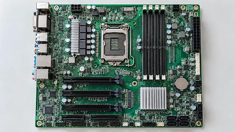
Computer peripherals, household electronics, control boards, and many everyday electronic assemblies use FR4-based PCBs. The rigid substrate supports components and connectors, while multilayer construction allows designers to route signals and power within relatively compact layouts.
Industrial Control and Communication Equipment
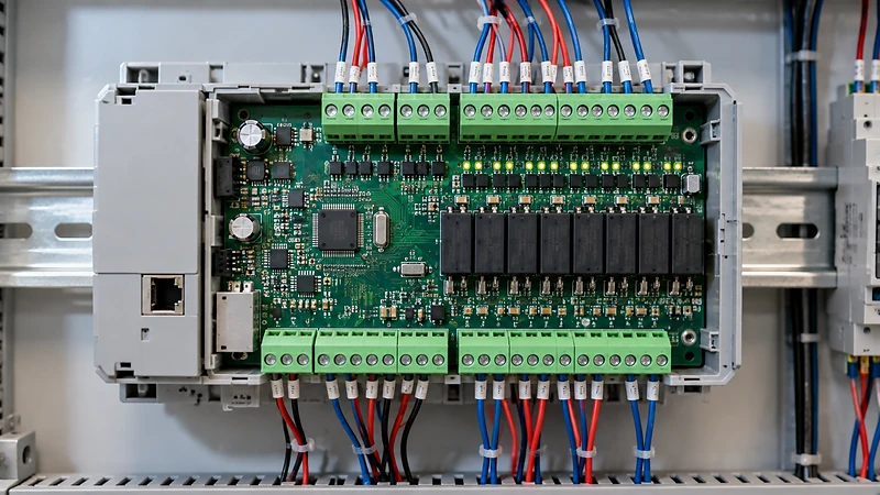
Industrial controllers, sensor interfaces, monitoring devices, and communication control boards commonly use FR4. These products benefit from mechanical stability, established manufacturing processes, and the availability of different laminate grades.
For equipment containing demanding high-frequency signal paths, additional evaluation of dielectric loss and signal integrity may still be necessary.
Automotive and Power Electronics
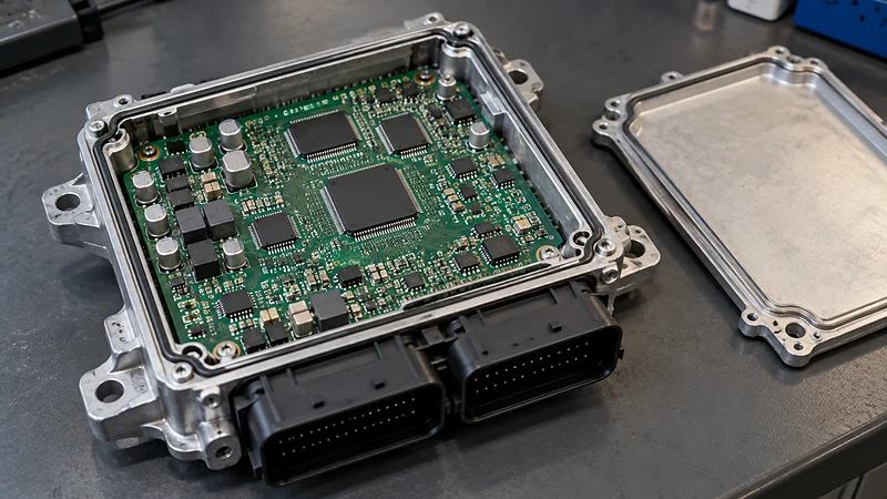
FR4-based laminates are also used in selected automotive control modules, power-control boards, and related assemblies. However, these applications can involve more demanding temperatures, vibration, insulation, and reliability requirements than conventional consumer electronics.
A material being labeled FR4 doesn’t automatically qualify it for automotive use. The laminate grade, board construction, and applicable validation requirements must all be considered.
How to Select the Right FR4 Material for Your PCB Project
By this point, the main takeaway should be clear: selecting FR4 is relatively straightforward, but selecting the right FR4 grade requires a closer look at the design.
You don’t necessarily need the most advanced laminate. You need one whose properties match the conditions your PCB will face during manufacturing, assembly, and operation.
Review Electrical and Thermal Requirements
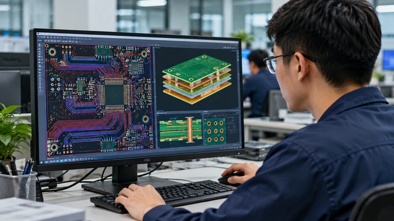
Start with the circuit’s electrical requirements, including operating frequency, signal transmission length, impedance targets, working voltage, and acceptable signal loss. High-speed circuits may need closer attention to Dk and Df, while high-voltage designs may require specific CTI and insulation characteristics.
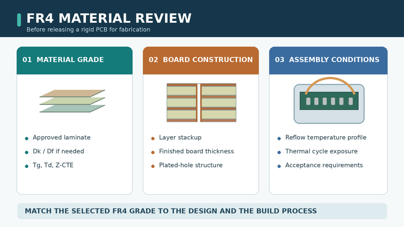
Next, consider the thermal environment. Operating temperature, soldering profile, repeated assembly cycles, and expected thermal cycling all influence the material choice. For demanding designs, Tg, Td, Z-CTE, and resistance to delamination should be reviewed together.
Confirm Manufacturing and Reliability Requirements
Before finalizing the material, check the PCB layer count, finished thickness, stackup, plated-hole structure, and assembly process. A thick multilayer board with demanding plated-hole geometry may have different thermal reliability requirements from a simple two-layer control board, even if both use FR4.
It’s also worth clarifying whether a specific laminate brand or grade is required, or whether an approved equivalent is acceptable. Providing Gerber files, fabrication drawings, stackup information, and special material requirements gives the PCB manufacturer a clearer basis for evaluating manufacturing feasibility and material suitability.
Frequently Asked Questions About FR4 PCB Material
Is FR4 Suitable for Multilayer PCBs?
Yes. FR4-based laminates and prepregs are commonly used in multilayer PCBs because they provide insulation and mechanical support between copper layers. However, thicker boards and complex plated-hole structures may require specific Z-axis expansion and thermal reliability characteristics. The selected laminate should match the PCB construction and assembly requirements.
What Is the Difference Between Standard FR4 and High-Tg FR4?
The primary difference is glass transition temperature. High-Tg FR4 has a higher Tg than conventional grades, which may be useful under more demanding thermal conditions. However, Tg alone doesn’t determine overall reliability. Engineers should also compare Td, Z-axis expansion, and time-to-delamination characteristics before selecting a material.
Can FR4 Be Used for High-Frequency PCBs?
Yes, depending on the operating frequency, transmission length, and acceptable signal loss. Standard FR4 generally has higher dielectric loss than specialized RF laminates, so demanding high-frequency designs may require materials with lower Df. The decision should be based on signal integrity requirements rather than a fixed frequency limit.
Is FR4 Suitable for Lead-Free PCB Assembly?
Many FR4 laminates are compatible with lead-free assembly, but their suitability depends on the specific material and thermal exposure. A soldering peak temperature above Tg doesn’t automatically indicate failure. Thermal expansion, decomposition resistance, delamination performance, and the number of soldering cycles should be evaluated together.
What Information Should Be Provided When Specifying FR4 PCB Material?
For conventional PCB designs, standard fabrication specifications may be sufficient if they clearly define the required material performance. More demanding projects may need explicit requirements for Tg, Td, Z-CTE, CTI, Dk/Df, or an approved laminate grade. PCB stackup, finished thickness, assembly conditions, and applicable reliability standards should also be communicated.
Conclusion
FR4 remains a standard choice because it meets the mechanical, electrical, and manufacturing needs of most conventional rigid PCBs. The key is knowing which FR4 grade fits your design—and recognizing when its limitations call for a different material.
Work With ABIS on Your PCB Manufacturing Project
ABIS Circuits provides PCB and PCBA manufacturing services, from prototypes to volume production. If you’re evaluating FR4 or alternative PCB materials, our team can review your design requirements and discuss manufacturing feasibility.
Contact ABIS Circuits to discuss your PCB project or request a quotation.


