
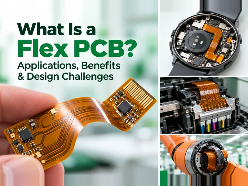
Flex PCB (flexible printed circuit board) is applied to settle accomodation problems with electronics when tights space or moving parts are required within a compact product. So compared to rigid PCBs, its benefits lie in allowing electrical connections to bend, fold, or follow the shape of a product, flexible and durable.
What Is a Flex PCB?
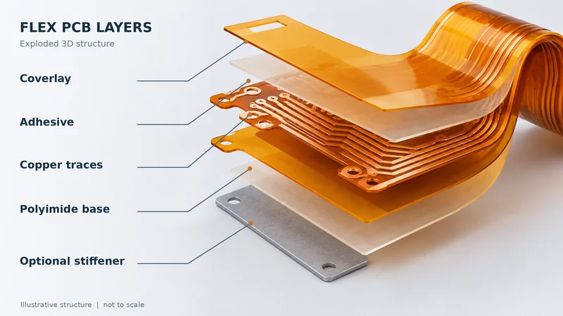
A flex PCBs uses a flexible insulating substrate, typically polyimide, with conductive copper traces. Unlike rigid PCBs, it can bend or fold to connect components positioned at different angles or locations.
Flexible circuits are available in single-sided, double-sided, and multilayer constructions. They are commonly used to reduce installation constraints, simplify certain interconnections, and support compact electronic assemblies.
However, flexibility alone does not guarantee suitability. The circuit structure must match the product’s electrical, mechanical, and assembly requirements.
What Problems Can Flex PCBs Solve in Electronic Products?
Fitting Circuits into Limited Spaces
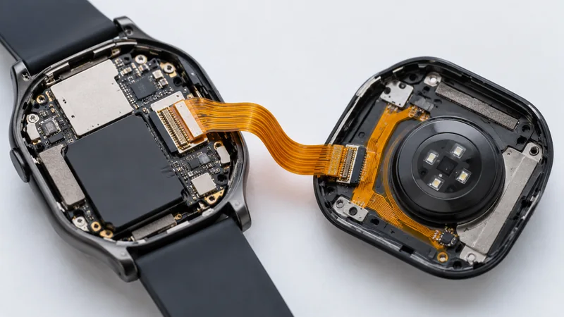
Compact devices like smart watch or other wearable devices frequently contain displays, batteries, sensors, and control boards arranged around structural components. A single rigid PCB may occupy too much space, while multiple boards introduce additional connections. So flex PCBs allow circuits to follow the available internal space. This gives engineers more freedom to position components without significantly changing the product enclosure.
Reducing Wiring and Assembly Complexity
Electronic assemblies with multiple modules often require separate cables and connectors. These connections occupy space and can increase installation time, particularly when components are difficult to access.A custom flex PCB can integrate multiple conductive paths into one structure, potentially reducing wiring and assembly operations.
Connecting Components Across Different Surfaces
The challenge is maintaining suitable bend geometry while preventing mechanical stress around connectors and solder joints. Electrical routing and mechanical layout must therefore be considered together.
Where Are Flex PCBs Used in Real Products?
Their applications range from compact sensor connections to high-density electrical interfaces and connections between moving components.
Why Are Flex PCBs Used for Electrical Connections in Inkjet Printheads?
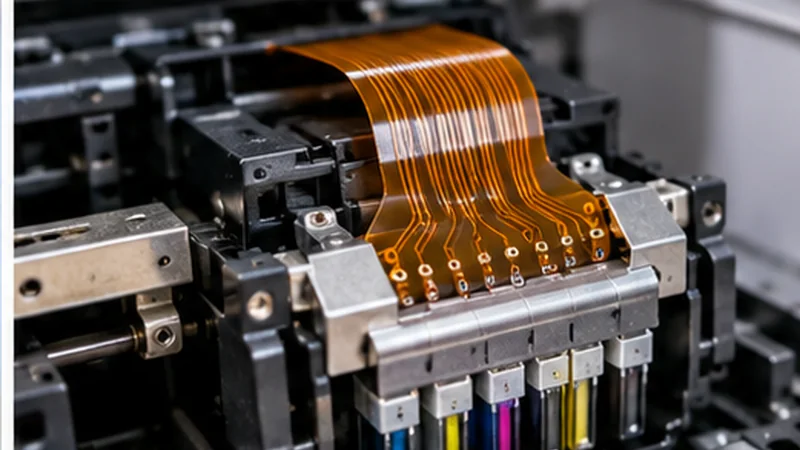
Inkjet printheads contain closely spaced electrodes that require precise connections to their driving circuits. Flex PCBs provide customizable conductor layouts that accommodate these connections within limited space.
But dense terminals create manufacturing challenges involving alignment, solder placement, and electrical isolation. This demonstrates why reliable manufacturing involves more than trace width and spacing. Terminal geometry, bonding methods, and assembly tolerances must also be evaluated before finalizing the circuit.
Flexible Connections in Consumer Electronics
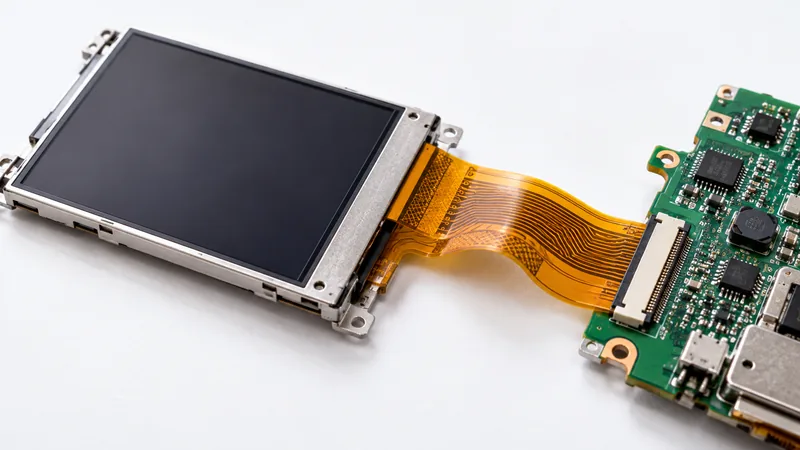
Camera modules and portable devices often contain components positioned inside irregularly shaped enclosures. Flex PCBs can connect image sensors, displays, and control electronics while accommodating these structures.
However, a stationary camera connection and a moving camera mechanism have different reliability requirements, which means engineers must distinguish between circuits that fold during assembly and those that experience repeated movement.
Flex PCB Applications in Industrial Equipment
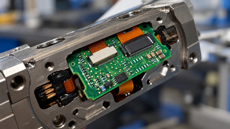
Industrial equipment may use flexible circuits for sensors, control assemblies, and selected moving mechanisms. Custom circuit shapes can simplify connections where rigid boards or conventional wiring are difficult to accommodate.
However, vibration, temperature changes, and repeated mechanical stress can affect performance. These operating conditions must be considered before selecting a flexible circuit.
What Makes Flex PCB Design and Manufacturing Challenging?
A flex PCB must satisfy electrical requirements while maintaining mechanical reliability. A circuit may perform correctly during electrical testing but develop problems after folding, assembly, or repeated movement.
Challenges increase when high-density routing, thin materials, reinforcement, and complex shapes must work together.
Why Can Flex PCBs Fail in Industrial Robot Joints Despite Being Flexible?
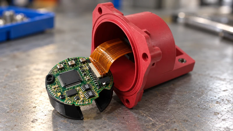
Industrial robot joints undergo repeated rotational movement, placing continuous stress on internal electrical connections. Although flex PCBs can bend, excessive deformation, twisting, or improper installation may eventually damage copper traces.
An ABB patent describing a robotic joint with a flexible printed circuit presents a spiral-shaped design that accommodates rotation while distributing bending across the circuit.
The key issue is not simply whether the circuit bends, but how it behaves throughout operation. Bending radius, movement range, copper construction, and expected operating cycles all influence reliability. A circuit designed for one-time folding may not withstand continuous movement. Engineers should therefore evaluate the installed configuration rather than relying solely on a flat PCB drawing.
Balancing Fine-Pitch Routing and Mechanical Flexibility
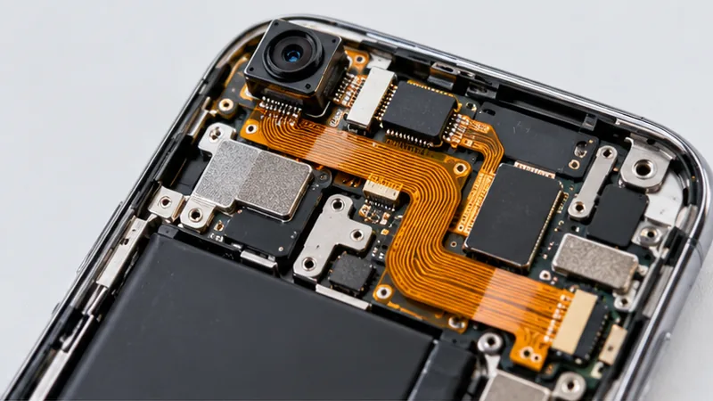
Compact electronics often require narrow traces, tight spacing, and multiple conductive layers. These features support complex routing but can increase circuit thickness and reduce flexibility.
Engineers may need to adjust the stack-up, relocate connections, or simplify routing within bending regions. Early design-for-manufacturing (DFM) evaluation helps identify these conflicts before fabrication.
Supporting Components Without Restricting Flexibility
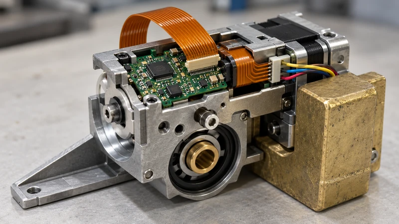
Connectors and mounted components generally require mechanical stability, even when the surrounding circuit must remain flexible. Without proper support, bending and handling may place stress on solder joints.
Stiffeners made from materials such as FR-4 or polyimide can reinforce selected areas without making the entire circuit rigid. However, reinforcement positioned too close to a bending region may concentrate stress at the transition. Successful designs provide support where needed while preserving flexibility elsewhere.
Why Are Some Flex PCB Designs Difficult to Manufacture?
Manufacturing becomes more demanding when a flex PCB combines fine-pitch conductors, multiple layers, unusual outlines, and precise reinforcement requirements.
So, common challenges exists:
- High-density routing
- Complex structures
- Dynamic bending
A manufacturer capable of producing standard flexible circuits may not support every combination of these requirements. Reviewing the design against actual manufacturing capabilities helps prevent unnecessary prototype revisions.
What Should You Confirm Before Manufacturing a Flex PCB?
Mechanical Requirements and Bending Conditions
Engineers should first determine whether the circuit will bend during installation or repeatedly during operation. These conditions affect material selection, copper construction, and reliability requirements.Important details include the intended folded shape, bending locations, movement range, and available installation space. For dynamic applications, expected operating cycles should also be defined.
Electrical Design and Assembly Requirements
Layer count, copper thickness, conductor density, and material selection influence manufacturing feasibility. Connector positions and component mounting requirements may determine whether additional reinforcement is necessary.
For assembled flex PCBs, manufacturers must also consider how components will be supported during soldering and installation.
Manufacturing Feasibility and DFM Review
Complete design information helps manufacturers identify potential conflicts before production. Typical flex PCB project requirements include:
- Fabrication files: Gerber or equivalent design data, board dimensions, layer count, materials, and surface finish.
- Mechanical specifications: Bending areas, folded dimensions, stiffener requirements, and installation conditions.
- Production details: Order quantity, assembly data, testing requirements, and expected delivery schedule.
At ABIS, flex PCB project coordination includes reviewing relevant details such as bending areas, copper thickness, coverlay, stiffener construction, and assembly requirements before manufacturing arrangements are finalized. Early communication helps engineering and purchasing teams clarify specifications and reduce unnecessary changes during prototype development.
Frequently Asked Questions About Flex PCBs
Can Flex PCBs Be Used for Continuous Bending?
Yes, reliability depends on material selection, copper construction, bending radius, and expected operating cycles. Dynamic applications require appropriate mechanical evaluation and testing to confirm that the design can withstand its intended operating conditions.
Are Flex PCBs More Expensive Than Rigid PCBs?
Flex PCBs generally cost more to fabricate than comparable standard rigid boards because of their materials and manufacturing processes. However, they may reduce overall assembly costs by replacing separate wiring or connectors. The actual economic advantage depends on the product design and production volume.
What Information Is Required for a Flex PCB Quotation?
Manufacturers typically require fabrication files, dimensions, layer count, material specifications, surface finish, and estimated quantity. For assembled or dynamically bending circuits, component placement information and relevant mechanical drawings help improve quotation accuracy.
Conclusion
Flex PCBs solve important challenges in compact designs, interconnections, and selected moving applications. However, reliable performance depends on balancing electrical requirements, mechanical flexibility, and manufacturing feasibility. Understanding these factors helps engineers select appropriate circuit structures, avoid unnecessary design changes, and improve the transition from prototype to production.
Explore Flex PCB Manufacturing Solutions with ABIS
If your product requires compact routing, complex connections, or specific bending conditions, contact ABIS to discuss your design requirements and available manufacturing options.


