
Metal Core PCB is widely used in electronics where conventional FR4 boards may struggle to manage heat generated by high-power components. However, choosing an aluminum or copper substrate does not automatically guarantee better thermal performance. Dielectric properties, copper thickness, and board construction all influence the result. Understanding these factors before production helps engineers select suitable materials and avoid unnecessary manufacturing costs.
What Is a Metal Core PCB and How Does It Work?
The Basic Structure of a Metal Core PCB
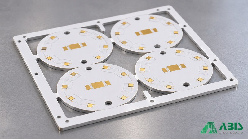
A Metal Core Printed Circuit Board (MCPCB), also known as a thermal PCB, uses a metal substrate to support the circuit and transfer heat away from electronic components. A typical single-sided aluminum MCPCB consists of three main functional layers: the copper circuit layer, dielectric layer, and metal core. These provide electrical connections, insulation, and heat spreading.
| Layer | Function |
|---|---|
| Solder Mask | Protects the circuit surface while leaving designated pads exposed |
| Copper Circuit Layer | Provides electrical connections and spreads heat |
| Dielectric Layer | Electrically isolates the copper circuit from the metal base while transferring heat |
| Metal Core | Provides mechanical support and spreads heat across the substrate |
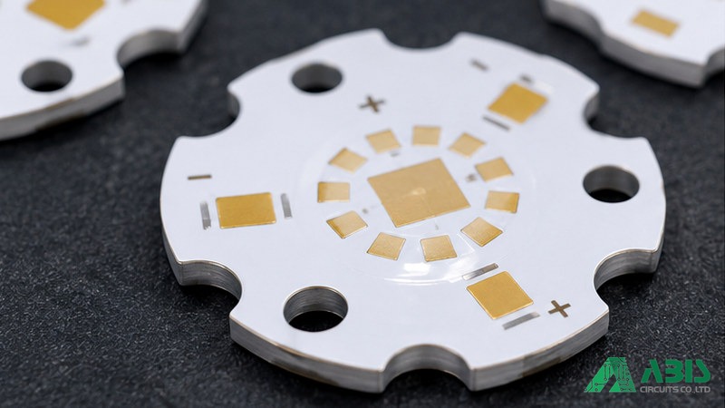
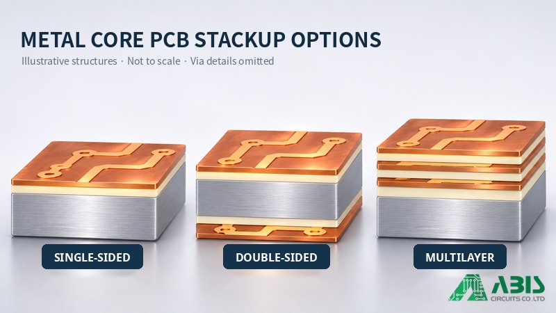
A solder mask normally covers the circuit layer, leaving designated component pads exposed for soldering. This is a typical single-sided construction, not a universal MCPCB structure. Double-sided and multilayer designs may incorporate additional copper and dielectric layers, sometimes combined with FR4 materials. Their actual construction should always be confirmed through a cross-sectional stackup drawing.
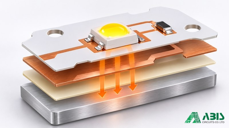
How Heat Travels Through an MCPCB
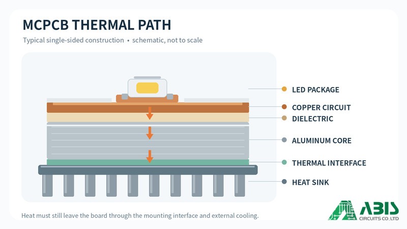
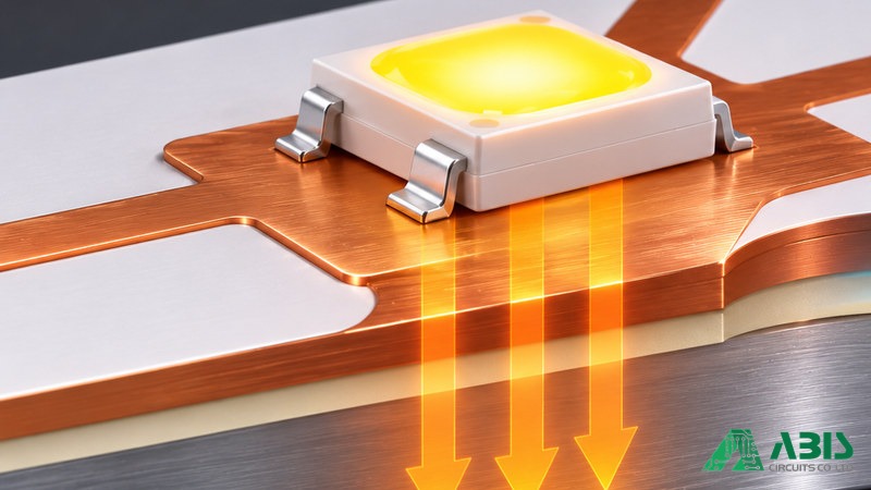
For a component with an exposed thermal pad, heat typically travels through the solder joint and copper circuit layer, passes through the dielectric, and reaches the metal core. It then transfers through a thermal interface material (TIM) to an external heat sink or chassis. Every stage contributes to overall thermal resistance, so a high-conductivity metal base cannot compensate for poor mounting contact or an unsuitable dielectric.
A simplified estimate of thermal resistance through an idealized material layer is:
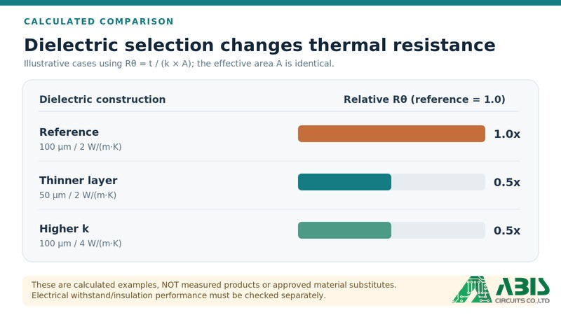
Rθ = t / (k × A)
Where t is material thickness (m), k is thermal conductivity (W/m·K), and A is effective heat-transfer area (m²). The result is expressed in K/W. The metal core primarily spreads heat away from localized hot spots, while an external heat sink helps reject it to the environment. This formula alone cannot predict the performance of a complete assembled product.
| Feature | Heat Spreader | Heat Sink |
|---|---|---|
| Primary role | Distributes localized heat | Rejects heat to the environment |
| Main process | Conduction | Conduction and convection, sometimes radiation |
| Typical example | Flat metal substrate | Finned metal structure |
Metal Core PCB vs. Metal-Backed PCB
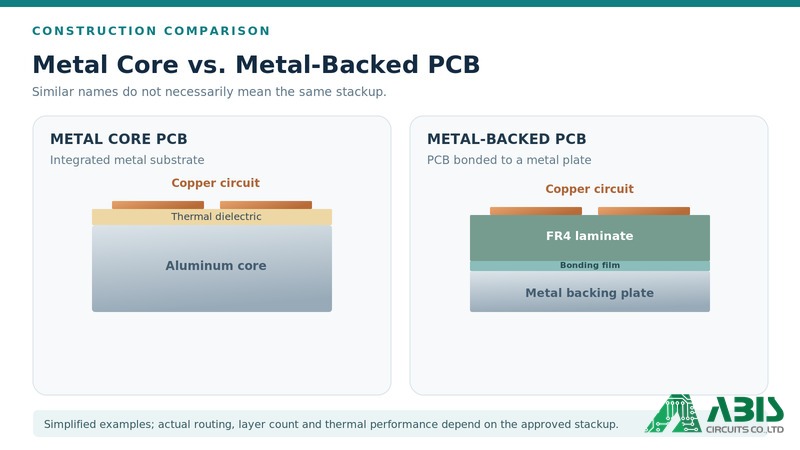
Metal Core PCB and Metal-Backed PCB are sometimes used interchangeably in supplier descriptions, but they do not necessarily refer to the same construction. A metal-backed design may use an FR4 circuit board attached to a separate metal plate, whereas a typical MCPCB incorporates a metal substrate into the board structure through a thermally conductive dielectric.
These differences affect heat transfer, routing possibilities, electrical isolation, and manufacturing complexity. Since supplier terminology is not always consistent, buyers should confirm the actual cross-section, copper layer arrangement, and metal-core position rather than relying on the product name alone.
What Are the Advantages and Applications of Metal Core PCBs?
Improved Thermal Management for High-Power Components
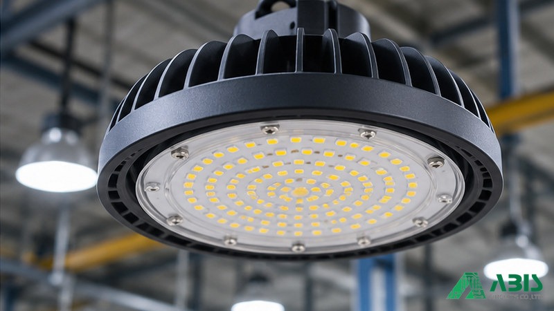
The primary advantage of an MCPCB is its ability to transfer heat away from components and distribute it across a larger metal surface. This is particularly useful in high-power LED assemblies, power supplies, and motor control circuits, where localized heat accumulation can affect component performance and service life.
A Lumileds LUXEON Z ES application brief (AB120, Table 1) compares these specific single-emitter PCB configurations:
| Board Construction | Typical Thermal Resistance, Thermal Pad to Board Bottom/Heat Sink |
|---|---|
| 1 mm FR4 with open PTH thermal vias | 9.0 K/W |
| 1 mm aluminum MCPCB with 1 oz copper, design B | 9.0 K/W |
| 1 mm aluminum MCPCB with 2 oz copper, design B | 5.6 K/W |
Test context: Lumileds AB120 (2015), Table 1. The evaluated MCPCB used a 1.0 mm aluminum base and a 100 µm dielectric with a specified thermal conductivity of 2.1 W/m·K. The FR4 design used open plated-through-hole thermal vias. Results are not universal performance specifications.
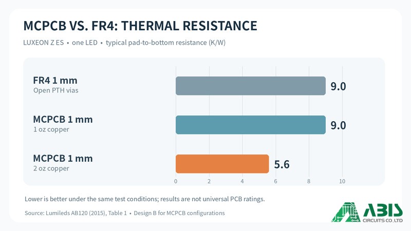
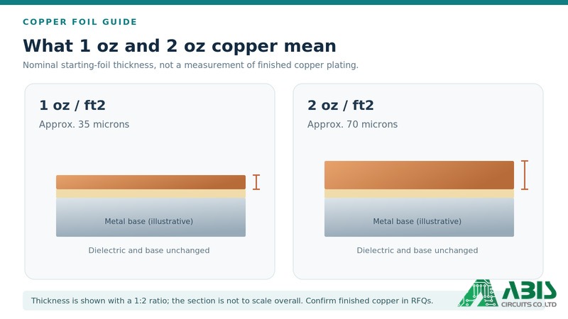
The data show that selecting a metal core does not automatically outperform every FR4 thermal-via design. Copper thickness, layout, and the complete thermal path must also be assessed. The 1 oz and 2 oz descriptions refer to nominal copper weight in these particular test constructions, not a universal finished copper-thickness requirement.
Mechanical Stability and Dimensional Performance
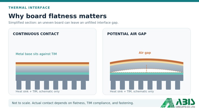
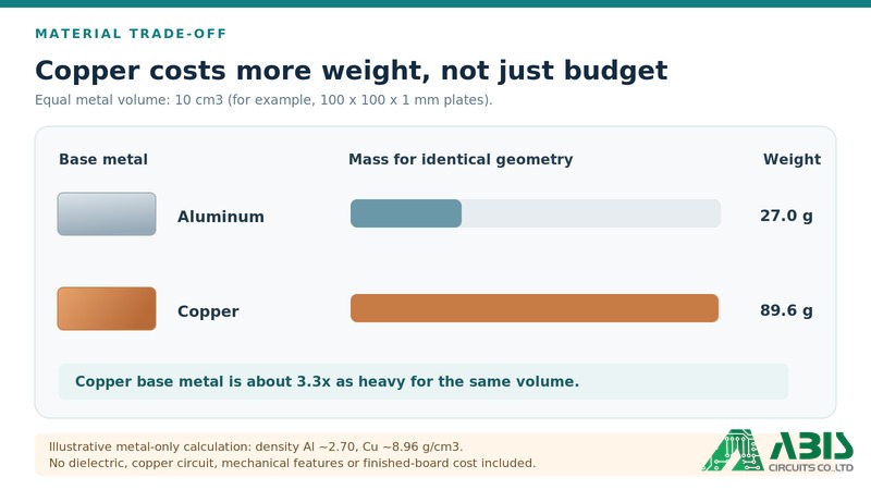
The metal substrate provides mechanical support and can function as a stiffening layer. Depending on its thickness and construction, an MCPCB can offer a stable mounting surface and help maintain contact with an external heat sink or enclosure. Copper generally has a higher elastic modulus than aluminum, while aluminum reduces weight for the same volume.
However, a metal core does not eliminate warpage. Substrate thickness, copper distribution, material expansion, and fabrication conditions influence flatness. For assemblies mounted directly against a heat sink, mounting-hole positions and surface flatness should be specified before production, because poor contact can increase thermal interface resistance.
Common Applications of Metal Core PCBs
MCPCBs are used where thermal management is important to the electronic design. High-power LED lighting is a well-established example; automotive electronics, power supplies, and motor drives may also use metal-core constructions to manage concentrated heat in power circuits.
| Application | Typical Purpose |
|---|---|
| LED Lighting | Heat management for high-power LEDs |
| Automotive Electronics | Thermal management in selected power and control modules |
| Power Supplies | Heat distribution in power-conversion circuits |
| Motor Drives | Supporting compact, heat-generating power electronics |
| Solar Energy Systems | Thermal management in selected power-electronics assemblies |
| Industrial Control | Managing heat in compact control assemblies |
The right design depends on operating temperature, power density, installation space, airflow, and the cooling available at system level. Application names alone do not determine whether an MCPCB is the best technical or cost-effective option.
Aluminum Core vs. Copper Core PCB: Which Should You Choose?
Aluminum Core PCB: A Practical Balance of Cost and Thermal Performance
Aluminum is commonly selected for metal-core applications because it offers a practical balance of heat spreading, low weight, availability, and cost. Common base-plate alloys include 5052-H32 and 6061-T6, although the preferred grade depends on mechanical requirements, production methods, and the approved supplier material system.
For LED lighting, power supplies, and other commercial power-electronics products, aluminum can often meet the thermal target without the extra mass and material cost of copper. Selection should still consider the dielectric, copper design, mounting interface, and actual operating conditions.
Copper Core PCB: When Higher Thermal Conductivity Matters
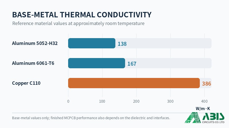
Copper has significantly greater base-metal thermal conductivity than aluminum and may offer mechanical or thermal-expansion benefits in particular designs. It can be considered when an engineering review shows a material advantage for local heat spreading, the mounting configuration, or mechanical requirements.
The trade-offs are greater weight, higher material cost, and potentially different machining and handling requirements. Copper should therefore be justified by the finished assembly’s thermal and mechanical needs rather than chosen solely because it has the highest base-metal conductivity.
Why Base Metal Conductivity Does Not Tell the Whole Story
The metal substrate is only one part of the thermal path. In many configurations, the dielectric layer and component interfaces contribute substantially more resistance than the base plate, so switching from aluminum to copper may not deliver a proportional improvement. Laird’s TLAM design guide explicitly cautions against assuming large system-level gains from copper alone.
Representative material data from Ventec’s insulated-metal-substrate datasheet illustrate the difference:
| Base Material | Thermal Conductivity (W/m·K) | CTE (ppm/°C) | Density (g/cm³) |
|---|---|---|---|
| Aluminum 5052-H32 | 138 | 23.8 | 2.7 |
| Aluminum 6061-T6 | 167 | 23.6 | 2.7 |
| Copper C1100 | 386 | 16.8 | 8.9 |
These are representative substrate-material properties, not measurements of an assembled MCPCB. Confirm exact alloy, temper, and supplier datasheet during quotation.
The Dielectric Layer: The Most Critical Part of MCPCB Design
How Dielectric Thickness Affects Thermal Resistance
The dielectric layer electrically isolates the copper circuit from the metal base while allowing heat to pass through. Under comparable conditions, a thinner dielectric or higher thermal conductivity generally reduces resistance through that layer. However, the effective area, interfaces, dielectric formulation, and electrical requirements also affect real-world performance.
Engineers should not reduce thickness simply to obtain a better thermal number. The resulting electrical withstand margin, material tolerances, and application requirements must be checked together. For comparison, the simplified relationship remains Rθ = t / (k × A), with its assumptions clearly stated.
Thermal Conductivity vs. Electrical Insulation
A suitable dielectric must move heat efficiently while maintaining the required electrical isolation. Thermal conductivity is not a substitute for dielectric strength, withstand voltage, insulation resistance, temperature capability, or material compatibility with the chosen manufacturing process.
The Lumileds AB120 example used a 100 µm dielectric with 2.1 W/m·K thermal conductivity and reported approximately 4 kV DC hi-pot performance for that specific MCPCB configuration. The figure cannot be adopted as a standard specification for other dielectric grades, thicknesses, or safety requirements.
| Dielectric Parameter | Why It Matters |
|---|---|
| Thermal Conductivity | Influences conduction through the insulating layer |
| Thickness and Tolerance | Influence heat transfer and electrical insulation margin |
| Withstand / Breakdown Voltage | Define and verify specified electrical performance |
| Insulation Resistance | Helps confirm isolation where required |
| Temperature Rating | Supports the intended thermal environment |
| Material Grade | Enables consistent supplier comparison and substitution control |
Balancing Heat Transfer and Dielectric Breakdown Voltage
A common sourcing mistake is to request the highest available dielectric conductivity without defining the electrical requirement. Another is to specify thickness without an approved material grade. Suppliers can then quote apparently similar boards with materially different insulation systems.
An RFQ should therefore identify the dielectric material, thickness tolerance, conductivity, electrical withstand requirements, and applicable operating conditions. Any substitute material must be reviewed and approved against both thermal and electrical requirements before production.
Metal Core PCB Stackup and Manufacturing Risks
Single-Sided, Double-Sided and Multilayer MCPCB Structures
MCPCB construction depends on the circuit layers required and the position of the conductive metal substrate. The simplest arrangement has one copper circuit layer over a dielectric and metal base. More complicated structures may place circuits on both sides or integrate additional circuit and insulating layers around or above the metal substrate.
| Construction | Example Layer Arrangement | Key Manufacturing Question |
|---|---|---|
| Single-Sided | Circuit copper / dielectric / metal base | Is the dielectric system specified and available? |
| Double-Sided | Circuit layers on two surfaces with a metal-core structure | How are interconnections isolated from the core? |
| Multilayer | Additional copper/dielectric layers integrated with metal | Does the actual approved stackup support routing and isolation? |
Suppliers may use terms such as double-sided and double-layer differently. A cross-sectional stackup drawing should therefore identify the number of circuit layers, dielectric grades, metal position, and interconnection strategy before quotation approval.
PTH Isolation and Insulating Fill Requirements
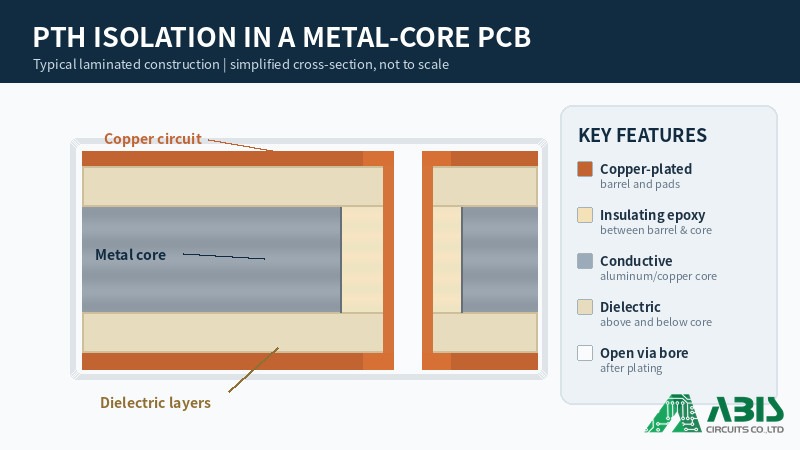
Plated through-holes (PTHs) need special attention because a conductive metal core can create an unintended electrical connection if a plated hole contacts it. Unlike a conventional FR4 through-hole, an MCPCB interconnection may need an engineered clearance and insulating structure around the copper-plated barrel.
One laminated approach uses a clearance opening through the metal, insulating material, and a subsequently drilled and plated hole. Other insulated-metal-substrate constructions use different process sequences. Buyers should require the fabricator to confirm the actual isolation design, clearance, fill requirements, and inspection method rather than assume every MCPCB uses the same process.
Stackup Balance, Flatness and Dimensional Control
Different copper layouts, dielectric materials, substrate thicknesses, and panel dimensions can affect flatness. The method chosen to separate panels also influences edge quality, burrs, dimensional capability, and cost. The appropriate choice depends on volume, geometry, tooling, and approved fabrication tolerances.
| Separation Method | Typical Use | Main Trade-Off |
|---|---|---|
| CNC Routing | Prototypes and complex custom outlines | Flexible geometry, higher processing time |
| V-Scoring | Suitable panelized outlines | Efficient breakaway, geometry and edge limitations |
| Punching | Higher-volume production | Dedicated tooling cost and design constraints |
For boards mounted directly to heat sinks, flatness, mounting-hole location, and edge finishing should be specified before fabrication. Burrs or uneven contact can interfere with the thermal interface even when the electrical circuit passes its test requirements.
What Should Buyers Check Before Ordering Metal Core PCB?
Confirm the Complete Material and Stackup Specifications
An RFQ stating only “Metal Core PCB, aluminum, 1.6 mm” leaves important engineering choices undefined. Different vendors could interpret the same request using different dielectric materials, foil weights, hole constructions, or mechanical tolerances. The following checklist makes vendor quotations more comparable.
| Specification | What Buyers Should Confirm |
|---|---|
| Metal Base | Material type, alloy, and thickness |
| Dielectric | Material grade, thickness/tolerance, and thermal conductivity |
| Copper | Starting foil weight and required finished thickness |
| Electrical Insulation | Withstand/breakdown requirements and test method |
| Stackup | Number and position of copper layers and metal substrate |
| PTH Isolation | Clearance, insulating construction, and connection requirements |
| Mechanical | Dimensions, flatness, mounting holes, burrs, and tolerances |
| Testing | Electrical continuity, isolation, and inspection acceptance criteria |
| Thermal Performance | Operating conditions and validation method |
For material-critical designs, specify an approved dielectric manufacturer and material grade rather than accepting a generic equivalent. If an alternative is proposed, request the data needed to compare thermal, electrical, mechanical, and process compatibility before approval.
Review DFM and Verify Manufacturing Quality
MCPCB designs should not be evaluated using FR4 manufacturing assumptions alone. Before production, DFM review should confirm stackup feasibility, PTH isolation, dielectric availability, copper requirements, machining, tolerances, and any special heat-sink mounting conditions. A design that looks simple in Gerber may still depend on a supplier-specific metal-core process.
After production, inspection should be based on approved drawings and specified acceptance criteria. Depending on the application, checks can include dimensional inspection, electrical continuity, insulation testing, material verification, and cross-section inspection of critical features.
| Inspection Item | What to Verify |
|---|---|
| Visual Inspection | Circuit features, board surfaces, and visible defects |
| Dimensional Inspection | Board outline, thickness, mounting holes, and flatness |
| Material Verification | Metal base and specified dielectric grade |
| Electrical Testing | Continuity and electrical isolation |
| Dielectric Testing | Withstand voltage or insulation resistance, when specified |
| Cross-Section Inspection | Critical internal layer or hole construction, where required |
If a specific thermal target must be verified, agree on power, mounting method, TIM, heat sink, ambient conditions, airflow, and temperature measurement points. Independent third-party QC can provide overseas buyers with additional verification that the delivered boards conform to the agreed requirements.
Frequently Asked Questions About Metal Core PCBs
1. Is Metal Core PCB the Same as Aluminum PCB?
No. Aluminum PCB is a type of metal core PCB that uses an aluminum substrate. Other designs may use copper or alternative metals, depending on electrical, thermal, and mechanical requirements.
2. Is Copper Core PCB Better Than Aluminum Core PCB?
Not necessarily. Copper conducts heat more effectively as a base metal, but it is heavier and generally more expensive. The complete thermal path—including dielectric and external cooling—determines whether copper creates a meaningful system-level advantage.
3. Can Metal Core PCBs Have Multiple Copper Layers?
Yes. Multilayer MCPCBs can use additional copper and dielectric layers, although the lamination and electrical-isolation requirements are more complex than for a single-sided board. The actual stackup should be confirmed during DFM review.
4. Can Plated Through-Holes Be Used in Metal Core PCBs?
Yes, provided the design accounts for the conductive metal core. Where electrical isolation is required, the hole construction must keep the plated barrel separated from the metal substrate through an approved insulating arrangement.
5. Does a Metal Core PCB Eliminate the Need for an External Heat Sink?
No. The metal substrate spreads heat but does not automatically provide sufficient heat rejection to ambient air. Depending on power and installation conditions, the assembly may still require a heat sink, thermal interface material, enclosure, or airflow management.
6. What Specifications Should Be Included in a Metal Core PCB RFQ?
Provide Gerber files, a stackup drawing, metal base grade and thickness, copper requirements, dielectric properties, electrical isolation requirements, mechanical tolerances, and relevant testing criteria. Include thermal operating conditions if the application has a specific temperature or thermal resistance target.
Conclusion
Choosing a Metal Core PCB involves more than selecting aluminum or copper. Dielectric properties, copper thickness, board construction, and the full thermal path determine whether the design meets its requirements. Confirming these details before production reduces the risk of mismatched quotations, unnecessary redesigns, and avoidable assembly issues.
Looking for a Reliable Metal Core PCB Supply Chain Partner?
ABIS coordinates an audited manufacturing network supporting different Metal Core PCB structures, material requirements, and production volumes. Our dedicated engineering team can review your Gerber files and stackup requirements, while independent third-party QC helps verify conformance to agreed specifications.
Send us your Gerber files for a preliminary DFM review and Metal Core PCB quotation.


